Bezier
Bezier Curves
Section titled “Bezier Curves”This script generates two random CV outputs using Bezier curves.
This work is inspired by the ADDAC507, a collaboration between ADDAC System and Monotrail
Inputs & Outputs
Section titled “Inputs & Outputs”The module has two separate output channels, referred to as A and B. Each has identical controls,
though channel B’s controls can only be accessed by holding b2. Note that when changing channels,
the knobs will “lock” in their previous positions, so you may need to sweep the knob to unlock it.
-
b1— press to change the clipping mode for both channels (see below) -
b2— hold to changek1andk2to channel B input -
k1— set the frequency of channel A or B -
k2— set the curve of channel A or B -
ain— configurable CV input to control either the frequency or curve (see below for how to set routing) -
din— on a rising edge, force channels A and B to choose new goal voltages. This will not generate an output gate oncv4(see below), but may change the gate state oncv5andcv6. -
cv1— CV output from channel A -
cv2— CV output from channel B -
cv3— the average of channel A and B CV outputs -
cv4— gate output of channel A -
cv5— gate output of channel B -
cv6— logic combination of gate outputs of channels A and B (see below for how to configure the logic mode)
Gate outputs are different for channels A and B:
- Channel A (
cv4) outputs a 10ms trigger every time a new sample is generated (determined by the frequency) - Channel B (
cv5) is high whenever its voltage output is higher than 50%. e.g. if the range is set to 0-10V,cv5will be high ifcv2is 5V or more.
Patching a clock/gate/trigger signal into din will force the output channels to choose a new goal
voltage. This can (and frequently will) cause an abrupt change in the CV output of channels A and B,
rather than the smoothly changing
voltages they normally output.
Additional Configuration
Section titled “Additional Configuration”The script has additional parameters that can be set by manually editing/creating
/config/Bezier.json. The default values for this file are below:
{ "MIN_VOLTAGE": 0.0, "MAX_VOLTAGE": 10.0, "AIN_MODE": "frequency", "LOGIC_MODE": "xor", "MAX_INPUT_VOLTAGE": 10.0}The following fields may be set:
MIN_VOLTAGE— the minimum voltage that channel A or channel B may output. Default: 0.0MAX_VOLTAGE— the maximum voltage that channel A or channel B may output. Default 10.0AIN_MODE— changes what parameter voltage toaincontrols. Must be one ofcurveorfrequency. Default:frequencyLOGIC_MODE— sets the logical operation used to determine the gate output ofcv6. Must be one ofand,or,xor,nand,nor, orxnor. Default:xor.MIN_FREQUENCY— the minumum frequency (Hz) for choosing new random values. Must be between 0.001 and 10.0. Default: 0.01MAX_FREQUENCY— the maximum frequency (Hz) for choosing new random values. Must be between 0.001 and 10.0. Default: 1.0MAX_INPUT_VOLTAGE— the maximum CV input voltage (default: 10.0)
Note that the maximum and minimum voltages must be defined such that:
MIN_VOLTAGEis less thanMAX_VOLTAGEMIN_VOLTAGEandMAX_VOLTAGEare positiveMIN_VOLTAGEandMAX_VOLTAGEdo not fall outside the range defined by the module’s master configurationMAX_INPUT_VOLTAGEis less than the module’s master configuration.
See Configuration for more information on input & output voltage options for the entire module.
If you plan on using CV to control Bezier, make sure you set the maximum input voltage according to
your modules’ output. For example if you plan on connecting it to an LFO that outputs 0-5V, you may
find it helpful to set the MAX_INPUT_VOLTAGE to 5.0 to allow the full modulation range. If your
LFO is bipolar (e.g. +/-5V), the input will be clamped at 0 as EuroPi does not support bipolar CV
input. In this case, the use of a voltage rectifier is recommended.
Clipping mode
Section titled “Clipping mode”The output can behave in one of 3 ways if the output wave moves outside the defined maximum/minimum voltage range:
limit— the output is clipped to the maximum/minimum valuefold— the output is flipped such that the shape of the curve is reflectedthru— the output wraps around through the opposite end of the range
Curve Shapes
Section titled “Curve Shapes”The shape of the bezier curves is defined by the “curve constant” k. This value lies in the range
[-1, 1], and is
interpreted as follows:
0.0— linear interpolation between voltagesk < 0— horizontal approach to each new voltagek > 0— vertical approach to each new voltage
The following image illustrates this concept, copied from the ADDAC507 manual:
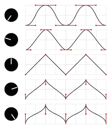
Negative values of k will generally result in a smoother overall shape to the output voltage.
Positive values will have more abrupt changes in voltage whenever a new goal value is generated.
CV Control
Section titled “CV Control”If CV control is set to frequency (the default), ain will accept positive voltage, increasing
the frequency of both channels as voltage increases.
If CV control is set to curve, ain will accept positive voltage, changing the curve constant of
both channels. The channels’ curve constants are set to the average between the knob value
([-1, 1]) and the CV value:
0Vis equivalent to a curve constant of-150%ofMAX_INPUT_VOLTAGEis equivalent to a curve constant of0100%ofMAX_INPUT_VOLTAGEis equivalent to a curve constant of+1